RF-RS End Sensing Devices
Sensor nodes are used in conjunction with the
RF-RX20 or RF-RX40 receiver units, and if required (depending on
installation topography), RF-RR series of routers.
Data is transmitted back to the receiver at configurable time intervals, or on a
configurable change in measured value. Each sensor retains these
configurations if the battery becomes discharged or requires replacement.
The sensors automatically find the best path back to the receiver, which
may be directly to the receiver or via ‘parent’ routers.
Leaflet
General
on request
Information
Startguide
Battery powered nodes are available in four
formats
Space mounting temperature, with setpoint and
momentary switch options
Space mounting RH&T, with setpoint and
momentary switch options
The radio RF-RS sensors are used in
conjunction with the RF-RX20 or RF-RX40 receiver
units, and if required (depending on installation topography), RFRR series of router radio sensors. Routers are used to route signals
from battery powered nodes and other routers to the receiver module,
where the signal strength of a direct path is not sufficient for
reliable communications.
The sensors, routers and receiver automatically
select which of the 16 transmission channels available gives the best
radio network performance, taking into account both signal strength and
interference levels from adjacent channels and equipment (such as Wi-Fi
etc.).
The sensors and routers automatically find the best path back to
the receiver, which may be directly to the receiver or via “parent”
routers. NB Each router can support a maximum of 16 “children”, a
maximum of 8 of which can be battery powered “end devices” and a maximum
of which can be 8 routers. Consideration should be given on network
planning for redundancy in case of router failure or damage.
RF-RS-T-541
RF-RS-T-522
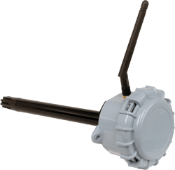
Immersion
Duct
RF-RS-T-551
RF-RS-T-531
Strap.on
Outside
RF-RS-T-555
RF-RS-T-532
Flying Lead
Outside
RF-RS-R-531
RF-RS-R-841
Wall
Outside
RF-RS-T-911
RF-RS-R-911
Space
Space
The RF-RS-T-551 range of strap-on
temperature sensors are used for detection of pipe temperatures, where
it isn’t possible to insert a pocket. The sensing element is housed in a
50mm long shaped brass probe, with 2 meters of PTFE screened cable.
The RF-RS-T-555 flying lead temperature
sensors are used for the detection of air temperature. Units contain a
high quality thermistor sensing element which is housed in a acetal
resin probe, with 2 metres of screened cable as standard. Longer cable
lengths are available to order (at extra cost) along with a potted
variant for low temperature applications and water submersion.
Labels
Labels are available in plain, pre-printed or
customer print types and a choice of either dark grey or white.
Installation
RF-RS
Remove all packaging from the sensor
Note the MAC address printed on the affixed
label and note where this MAC address is installed.
Remove the lid by twisting and separating
from the main body and install the Li-SOCl2 2/3 A battery, observing
the correct polarity.
Mount the sensor in the required position
(this will have been determined by the site survey tool, (see the
quick start guide and manual), where dust & contaminants are at a
minimum (i.e. after filters etc.) and which will give a
representative sample of the prevailing air condition.
Drill two holes at 85mm centres and a 19mm
diameter hole centrally between them for the duct probe.
Fix the IP65 housing to the duct with
appropriate screws. Making sure to align the holes in the probe so
they point into the air flow. The housing is designed to make it
easy for an electric screwdriver to be used if desired.
To power on the unit, fit J400.
Allow 3 minutes before checking functionality.
Allow 30 minutes before carrying out
precommissioning checks.
Ensure, at a minimum, that all routers and
the receiver on the radio network are powered on, and allow about 5
minutes for the network to autocommission before attempting to read
values or make configuration changes.
RF-RS-T-551 and RF-RS-T-555
Remove all packaging from the sensor
Note the MAC address printed on the affixed
label and note where this MAC address is installed.
Remove the lid by twisting and separating
from the main body and install the Li-SOCl2 2/3 A battery, observing
the correct polarity.
Mount the sensor in the required position
(this will have been determined by the site survey tool, (see the
quick start guide and manual).
Drill two holes at 85mm centres, fix the IP65
housing to the duct with appropriate screws. Making sure to align
the holes in the probe so they point into the air flow. The housing
is designed to make it easy for an electric screwdriver to be used
if desired.
To power on the unit, fit J400.
Secure the brass lug to the surface to be
monitored, using the strap supplied.
Ensure, at a minimum, that all routers and
the receiver on the radio network are powered on, and allow about 5
minutes for the network to autocommission before attempting to read
values or make configuration changes